
A lot of sources say configuring MPLS BGP peering using /32 loopbacks is recommended, or even required.
So what, if anything, happens when we set up MP-BGP peering using loopbacks with /24 addresses?
We will test this on a simple topology with 2 PEs, 2 CEs and 1 P routers.
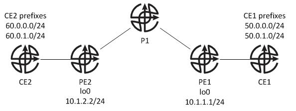
PE1 and PE2 have BGP peering configured using their loopbacks, 10.1.1.1/24 and 10.1.2.2/24 .
Client sites, placed in vrf RED, are running BGP AS65015 with PEs and have the following networks configured:
CE1
50.0.0.0/24
50.0.1.0/24
CE2
60.0.0.0/24
60.0.1.0/24
As we can see MP-BGP session comes up and prefixes are exchanged:
PE1#sh bgp vpnv4 unicast all sum | b Nei
Neighbor        V           AS MsgRcvd MsgSent   TblVer  InQ OutQ Up/Down  State/PfxRcd
10.1.2.2        4           24       6       7       10    0    0 00:01:04        3
120.0.0.2       4        65015      10      11       10    0    0 00:05:57        3

PE1#sh bgp vpnv4 unicast all | b Net
     Network          Next Hop            Metric LocPrf Weight Path
Route Distinguisher: 1:1 (default for vrf RED)
 *>  50.0.0.0/24      120.0.0.2                0             0 65015 ?
 *>  50.0.1.0/24      120.0.0.2                0             0 65015 ?
 *>i 60.0.0.0/24      10.1.2.2                 0    100      0 65015 ?
 *>i 60.0.1.0/24      10.1.2.2                 0    100      0 65015 ?
 *   120.0.0.0/24     120.0.0.2                0             0 65015 ?
 *>                   0.0.0.0                  0         32768 i
 *>i 121.0.0.0/24     10.1.2.2                 0    100      0 i
PE2#sh bgp vpnv4 unicast all sum | b Nei
Neighbor        V           AS MsgRcvd MsgSent   TblVer  InQ OutQ Up/Down  State/PfxRcd
10.1.1.1        4           24       7       6       10    0    0 00:01:46        3
121.0.0.2       4        65015       6       7       10    0    0 00:01:14        3

PE2#sh bgp vpnv4 unicast all | b Net
     Network          Next Hop            Metric LocPrf Weight Path
Route Distinguisher: 1:1 (default for vrf RED)
 *>i 50.0.0.0/24      10.1.1.1                 0    100      0 65015 ?
 *>i 50.0.1.0/24      10.1.1.1                 0    100      0 65015 ?
 *>  60.0.0.0/24      121.0.0.2                0             0 65015 ?
 *>  60.0.1.0/24      121.0.0.2                0             0 65015 ?
 *>i 120.0.0.0/24     10.1.1.1                 0    100      0 i
 *   121.0.0.0/24     121.0.0.2                0             0 65015 ?
 *>                   0.0.0.0                  0         32768 i
We can also see that each of the customer sites learns the routes from the other site:
CE1#sh ip route bgp | b sub
      60.0.0.0/24 is subnetted, 2 subnets
B        60.0.0.0 [20/0] via 120.0.0.1, 00:02:11
B        60.0.1.0 [20/0] via 120.0.0.1, 00:02:11
      121.0.0.0/24 is subnetted, 1 subnets
B        121.0.0.0 [20/0] via 120.0.0.1, 00:02:12

CE2#sh ip route bgp | b sub
      50.0.0.0/24 is subnetted, 2 subnets
B        50.0.0.0 [20/0] via 121.0.0.1, 00:01:47
B        50.0.1.0 [20/0] via 121.0.0.1, 00:01:47
      120.0.0.0/24 is subnetted, 1 subnets
B        120.0.0.0 [20/0] via 121.0.0.1, 00:01:47
But what happens when we try to ping from one customer site to the other?
CE1#ping 60.0.0.1 source l50
Type escape sequence to abort.
Sending 5, 100-byte ICMP Echos to 60.0.0.1, timeout is 2 seconds:
Packet sent with a source address of 50.0.0.1
.....
Success rate is 0 percent (0/5)
Ping fails.
How about traceroute:
CE1#traceroute 60.0.0.1 source l50
Type escape sequence to abort.
Tracing the route to 60.0.0.1
VRF info: (vrf in name/id, vrf out name/id)
  1 120.0.0.1 5 msec 2 msec 5 msec
  2  *  *  *
  3  *  *  *
Trace stops on the PE1. We should now focus our investigation on PE1. We know that PE1 received route to 60.0.0.0/24 over MP-BGP:
PE1#sh bgp vpnv4 unicast all 60.0.0.0/24
BGP routing table entry for 1:1:60.0.0.0/24, version 8
Paths: (1 available, best #1, table RED)
  Advertised to update-groups:
     1
  65015
    10.1.2.2 (metric 21) from 10.1.2.2 (10.1.2.2)
      Origin incomplete, metric 0, localpref 100, valid, internal, best
      Extended Community: RT:1:1
      mpls labels in/out nolabel/203
Next hop shows 10.1.2.2, and routing table has the following for 10.1.2.2:
PE1#sh ip route 10.1.2.2
Routing entry for 10.1.2.2/32
  Known via "ospf 1", distance 110, metric 21, type intra area
  Last update from 140.1.11.1 on FastEthernet0/0, 00:23:30 ago
  Routing Descriptor Blocks:
  * 140.1.11.1, from 10.1.2.2, 00:23:30 ago, via FastEthernet0/0
      Route metric is 21, traffic share count is 1
Corresponding label for this prefix:
PE1#sh mpls forwarding-table 10.1.2.2
Local  Outgoing    Prefix            Bytes tag  Outgoing   Next Hop
tag    tag or VC   or Tunnel Id      switched   interface
102    301         10.1.2.2/32       0          Fa0/0      140.1.11.1
All seems to be in order, let's move to the next hop 140.1.11.1, which happens to be P1:
P1#sh ip route 10.1.2.2
Routing entry for 10.1.2.2/32
  Known via "ospf 1", distance 110, metric 11, type intra area
  Last update from 140.1.12.2 on FastEthernet0/1, 00:25:02 ago
  Routing Descriptor Blocks:
  * 140.1.12.2, from 10.1.2.2, 00:25:02 ago, via FastEthernet0/1
      Route metric is 11, traffic share count is 1

P1#sh mpls forwarding-table 10.1.2.2
Local  Outgoing    Prefix            Bytes tag  Outgoing   Next Hop
tag    tag or VC   or Tunnel Id      switched   interface
301    Untagged    10.1.2.2/32       3983       Fa0/1      140.1.12.2
We can see that P1 has the route to 10.1.2.2 and it points to PE2, as it should. However LFIB does not have an outgoing label for this prefix and consequently cannot forward labelled packets destined 10.1.2.2. So now you might wonder, what's wrong here. PE2 owns this prefix so it should have advertised a label for it. We will move to PE2 and see if the label gets generated:
PE2#sh mpls ldp bindings 10.1.2.2 32
  tib entry: 10.1.2.2/32, rev 11
        remote binding: tsr: 10.1.10.10:0, tag: 301
PE2 has no local binding for 10.1.2.2/32. We know that labels are generated for all IGP prefixes, and here's what the routing table shows on PE2:
PE2#sh ip route 10.1.2.2
Routing entry for 10.1.2.0/24
  Known via "connected", distance 0, metric 0 (connected, via interface)
  Routing Descriptor Blocks:
  * directly connected, via Loopback0
      Route metric is 0, traffic share count is 1

PE2#sh mpls ldp bindings 10.1.2.0 24
  tib entry: 10.1.2.0/24, rev 4
        local binding:  tag: imp-null
Wait, there's no route for 10.1.2.2/32 and consequently no label for /32 is being generated. Instead PE2 has a route for /24, which is the mask we configured on lo0. Other routers however don't have this route but instead learn /32 route. This causes LSP to break.
The reason for this discrepancy is the default behaviour of OSPF when advertising loopback addresses. OSPF ignores mask configured for the IP address on the loopback interface and advertises it as a /32 prefix instead.
We have two possible solutions to this problem:
- Change the mask on loopback interfaces to /32 to avoid issues caused by OSPF and its default behaviour.
- Add "ip ospf network point-to-point" to the loopback's configuration. This will tell OSPF to advertise this prefix with the correct mask.
For the sake of this example we will change OSPF network type to show that /24 IP addresses can work in this scenario.
After our configuration changes we can see that all of the routers in the path have correct entries in the LIB and LFIB:
PE1#sh mpls forwarding-table 10.1.2.2
Local  Outgoing    Prefix            Bytes tag  Outgoing   Next Hop
tag    tag or VC   or Tunnel Id      switched   interface
106    302         10.1.2.0/24       0          Fa0/0      140.1.11.1

PE1#sh mpls ldp bindings 10.1.2.0 24
  tib entry: 10.1.2.0/24, rev 13
        local binding:  tag: 106
        remote binding: tsr: 10.1.10.10:0, tag: 302

P1#sh mpls forwarding-table 10.1.2.2
Local  Outgoing    Prefix            Bytes tag  Outgoing   Next Hop
tag    tag or VC   or Tunnel Id      switched   interface
302    Pop tag     10.1.2.0/24       254        Fa0/1      140.1.12.2

P1#sh mpls ldp bindings 10.1.2.0 24
  tib entry: 10.1.2.0/24, rev 13
        local binding:  tag: 302
        remote binding: tsr: 10.1.2.2:0, tag: imp-null
        remote binding: tsr: 10.1.1.1:0, tag: 106

PE2#sh mpls ldp bindings 10.1.2.0 24
  tib entry: 10.1.2.0/24, rev 4
        local binding:  tag: imp-null
        remote binding: tsr: 10.1.10.10:0, tag: 302
And a final test, another ping attempt and traceroute between CE1 and CE2:
CE1#ping 60.0.0.1 source l50

Type escape sequence to abort.
Sending 5, 100-byte ICMP Echos to 60.0.0.1, timeout is 2 seconds:
Packet sent with a source address of 50.0.0.1
!!!!!
Success rate is 100 percent (5/5), round-trip min/avg/max = 80/85/92 ms

CE1#traceroute 60.0.0.1 source l50

Type escape sequence to abort.
Tracing the route to 60.0.0.1

  1 120.0.0.1 20 msec 36 msec 8 msec
  2 140.1.11.1 [MPLS: Labels 302/203 Exp 0] 60 msec 60 msec 60 msec
  3 121.0.0.1 [AS 24] [MPLS: Label 203 Exp 0] 44 msec 40 msec 40 msec
  4 121.0.0.2 [AS 24] 72 msec 68 msec 60 msec

CE2#ping 50.0.1.1 source l61

Type escape sequence to abort.
Sending 5, 100-byte ICMP Echos to 50.0.1.1, timeout is 2 seconds:
Packet sent with a source address of 60.0.1.1
!!!!!
Success rate is 100 percent (5/5), round-trip min/avg/max = 60/72/84 ms

CE2#traceroute 50.0.1.1 source l61

Type escape sequence to abort.
Tracing the route to 50.0.1.1

  1 121.0.0.1 40 msec 40 msec 20 msec
  2 140.1.12.1 [MPLS: Labels 300/104 Exp 0] 68 msec 60 msec 60 msec
  3 120.0.0.1 [AS 24] [MPLS: Label 104 Exp 0] 52 msec 48 msec 48 msec
  4 120.0.0.2 [AS 24] 88 msec 80 msec 60 msec
As we can see, bidirectional connectivity has been achieved with MP-BGP peering configured on /24 loopbacks.
We can now appreciate why use of /32 loopback is recommended for LDP/MP-BGP/MPLS peerings. This practice ensures that label generation is in sync with our IGP and it can save us a lot of troubleshooting in the future.